
The direction of motion of conventional aircraft is controlled by moving aerodynamic surfaces. Typically, the primary control surfaces are the ailerons, the elevators and the rudder, which are used to change aircraft roll, pitch and yaw angles, respectively, as illustrated on Figure 1.

Figure 1 – Aircraft Control Surfaces And Angles
Other flight control surfaces such as spoilers and trim tabs are also used in several aircraft, although they are not always present in a design. However, the ailerons, elevator and rudder are typically found in almost every conventional airplane.
By moving the ailerons, typically one up and the other down, a net imbalance of vertical aerodynamic force is created, which then makes the aircraft roll around its longitudinal axis. When the elevator is moved, a vertical force is created aft of the aircraft’s center of gravity, and this makes the airplane rotate so that it has its pitch altered. The same principle applies to the rudder, but this is used to create an additional lateral force which rotates the plane changing its yaw angle.

Figure 2 – Roll

Figure 3 – Pitch

Figure 4 - Yaw
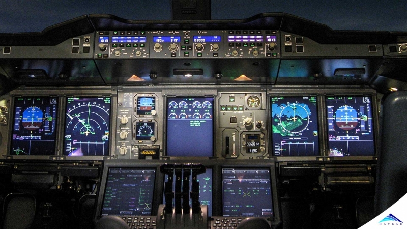
The control surfaces are controlled by the crew in the cockpit. Typically, the ailerons and the elevators are moved as a result of the pilot or copilot input in a control yoke or sidestick, while the rudder is actioned by pedals.
What is there between the control column and the control surfaces?
Since the early days of aviation and until 1958, with the first flight of the Avro Canada CF-105 Arrow, all non-experimental aircraft had pure mechanical or hydro-mechanical control systems. In other words, the force applied by the pilot to the yoke and/or pedals were linked to the control surfaces via a sequence of force transmitting and converting mechanisms.

Figure 5 – Mechanical Flight Control System
In the flight control system shown in Figure 5, the pilot applies a force to the column, which then transmits this force to a steel cable. This cable is linked with other cables via rods and pulleys, and the input force is transmitted to each one of the cables in the system. Finally, the last cable is connected to the control surface axis. The applied force by the pilot is, then, ultimately transmitted to this axis and rotates the surface.
As airplanes got bigger and bigger, the force required by the pilot to move the control surfaces became too large. This way, a force multiplier was added to the control system: hydraulics. Figure 6 illustrates a typical application of hydraulic force in an aircraft flight control system.

Figure 6 – Hydro Mechanical Flight Control System
In a system as shown on Figure 6, which is called a hydro-mechanical system, the input force by the pilot is used to move mechanisms, which control the opening and closure of servo valves. These valves are part of a hydraulic circuit and are used to allow or stop the flow of high pressure hydraulic fluid through the circuit. The fluid is used to move pistons which are connected to the control surfaces, creating their motion.
Even though mechanical and hydro-mechanical systems work perfectly fine and have been used in a large number of aircraft, there were some room for improvement. These kinds of systems use a big number of components such as cables, pulleys, rods, valves and hydraulic pipes. All of these parts contribute to the aircraft weight and create challenges in terms of routing. Also, they provide none or just some protection for the aircraft flight envelope.
The Fly-By-Wire Flight Control System;
As it is common practice in the aeronautical industry to pursuit solutions to increase safety, reduce aircraft weight and improve flight quality, the flight control system has ever evolved in this same direction. The design and application of the so-called fly-by-wire (FBW) flight control system is one of the great examples of safer, lighter and more efficient technology.
Differently from the mechanical or hydro-mechanical control systems, the FBW system works by converting the pilot input on the yoke or pedals into electrical signals. These signals travel through wires and goes into flight control computers (FCC). The FCC reads the signal which is a translation of the pilot’s inputs and, considering all of the parameters that describes the actual condition of the aircraft (altitude, airspeed, weight, pitch, bank angle, etc), generates another electrical signal containing the information of how much the control surfaces should be deflected.
The information coming from the FCC is then read by another computer, usually called Actuator Control Electronic (ACE). The ACE receives the input from the FCC of how what angle the respective control surface is to be placed at. After processing this signal, the ACE directly or indirectly sends a command to a servo-valve. This command controls the opening or closure of the valve, which, then, allows or restrains the flow of hydraulic fluid to move an actuator. The actuator, ultimately, move the control surface.

Figure 7 – Fly-By-Wire Flight Control System
The Advantages;
The way a fly-by-wire control system works, at first, might seem to be adding an enormous amount of complexity to a system that had been functioning just fine. In some sense, this can be true. However, the advantages brought by this technology outweigh the complexity, a fact that is proven by the increase in the number of designs which use FBW.
Due to the use of computers in the flight control chain, the flexibility of the system is huge. The engineers decide on the logics that go into the FCCs and ACEs. This way, the aircraft controllability can be fine tuned considering all the variables that affect the flight dynamics. In other words, the system takes into account airspeed, weight, altitude, CG position, orientation, flight phase and other parameters to the determine the final commands.
This flexibility also improves safety. By using logics to ultimately generate the control commands, the flight envelope can be protected. When aircraft is commanded by the crew and this intended command may lead to an unsafe condition, such as low/high speed, excessive bank angle or improper acceleration, the system will anticipate this situation and control the aerodynamic surfaces in such a way to avoid or leave it.
Ultimately, fly-by-wire leads to more fuel-efficient aircraft. The overall weight of the system is usually smaller when compared to traditional flight control systems. Also, due to the continuous and precise control of the aoerdynamic surfaces, the aircraft natural stability can be relaxed, leading to smaller horizontal and vertical stabilizers and, thus, lighter structures and reduced drag.
Final Remarks;
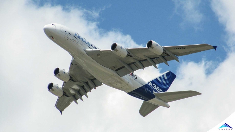
Fly-by-wire flight control system is becoming more and more common aircraft design. Some examples of airplanes which use this technology are the Airbus A320, Boeing 777 and the Embraer 190-E2. As the designers and manufacturers become more experienced with the system, its advantages get increasingly evident, resulting in safer, lighter and more efficient airplanes.
 What Are Seaplanes And Their History Of Development ?
 Interesting Facts You Never Knew About Commercial Aircrafts And Aviation
 Extended Ground Proximity Warning System - EGPWS
 Airspace Classifications And The Air Traffic Control Services
 How An Instrument Landing System ( ILS ) Works
 EFB (Electronic Flight Bag)
 All About Aviation Fuels